
A shop can make front-lit and reverse-halo channel letters with the same group of machines. The mix changes from one style to the other, and so does the order of the work.
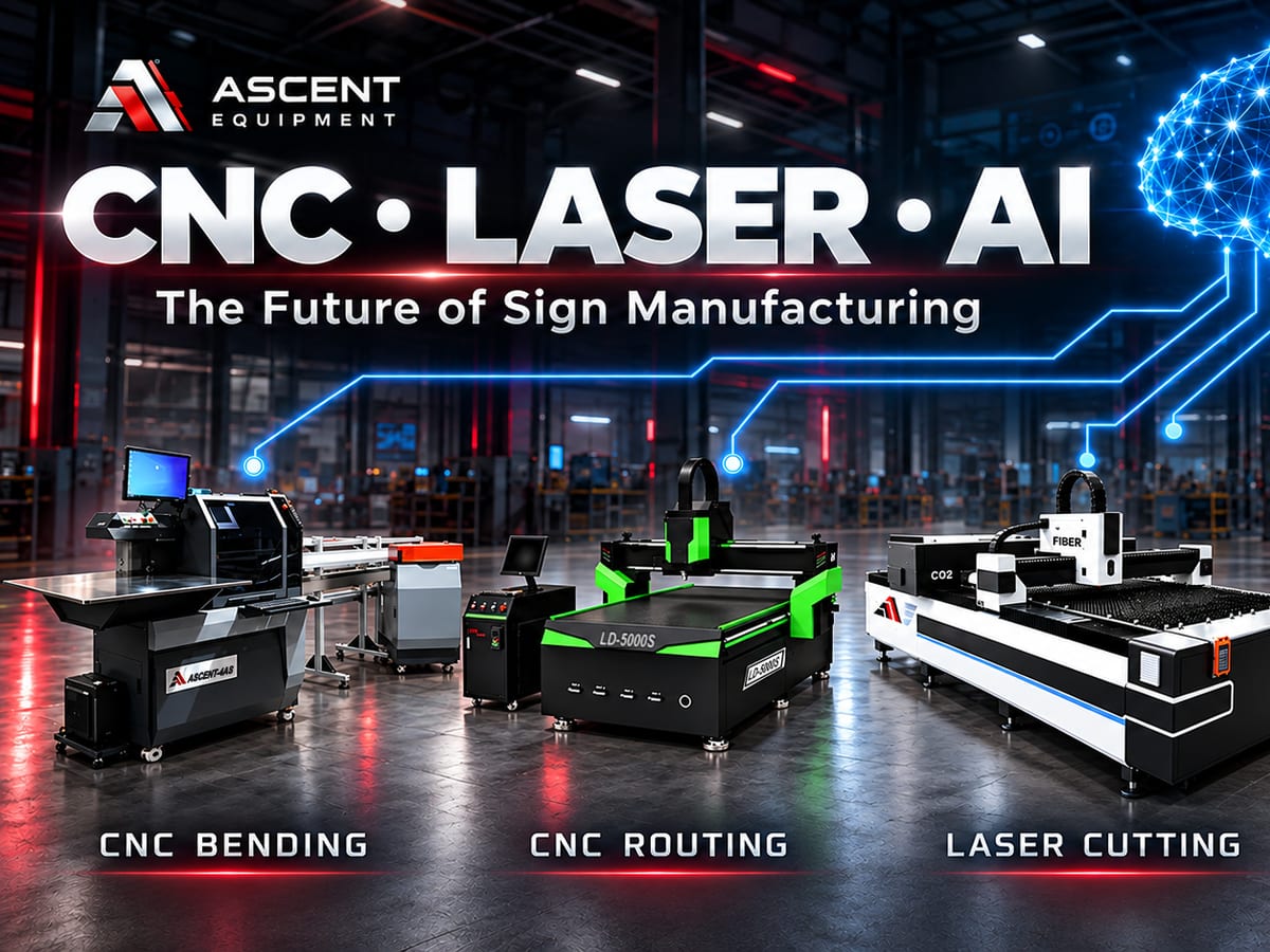
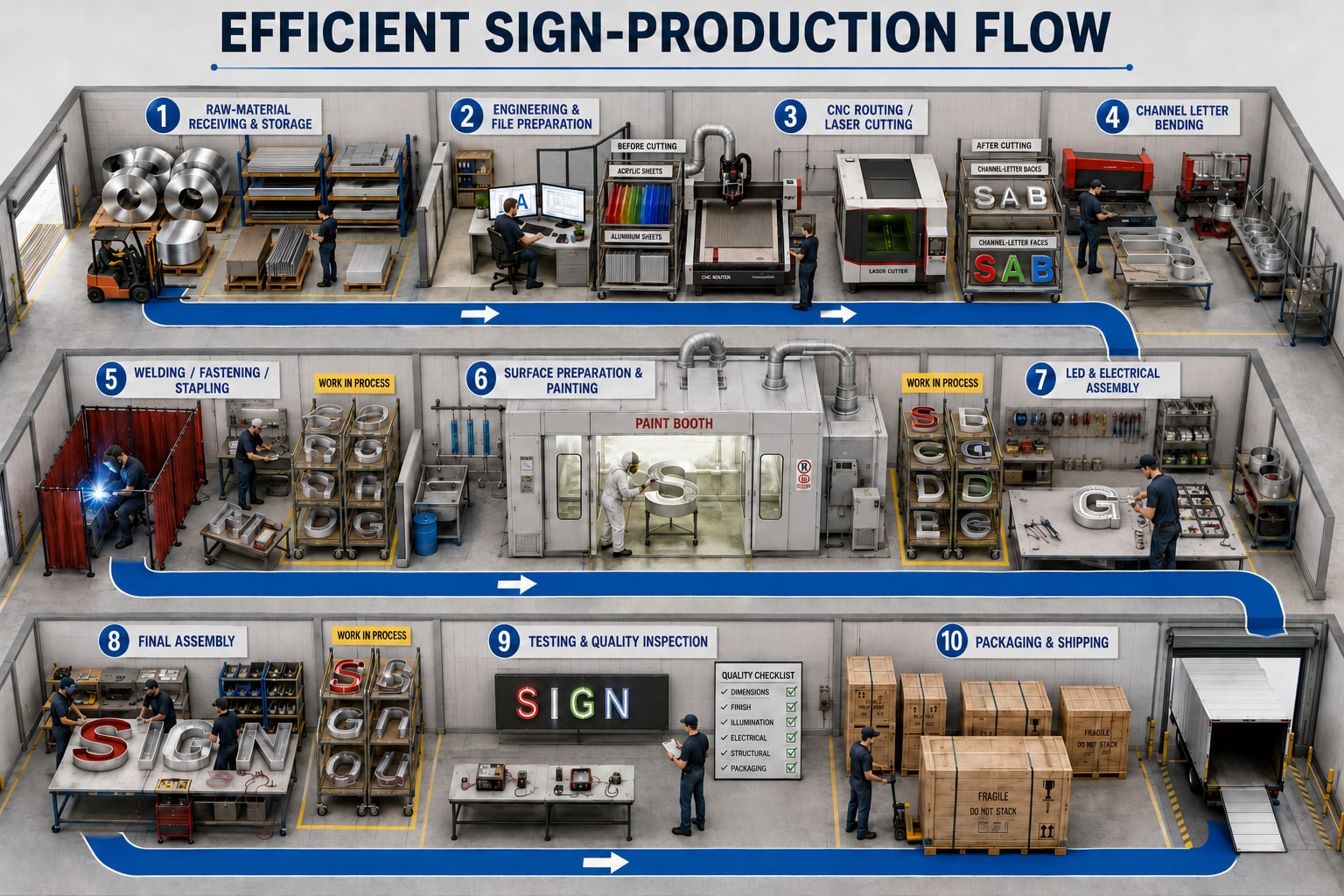
Below, each style gets a picture of the production flow and a step-by-step list. The machines are the Ascent CNC router, the EDGE4 bending machine, the TMB3 trim machine, the Ascent stapler, and the QCW laser welder.
The EDGE4 forms the letter returns, and it begins shipping in November 2026. The TMB3 makes the aluminum trim for front-lit letters from flat coil. The stapler joins the backs of front-lit letters, and the QCW welds reverse-halo letters.
Front-lit channel letters with aluminum trim
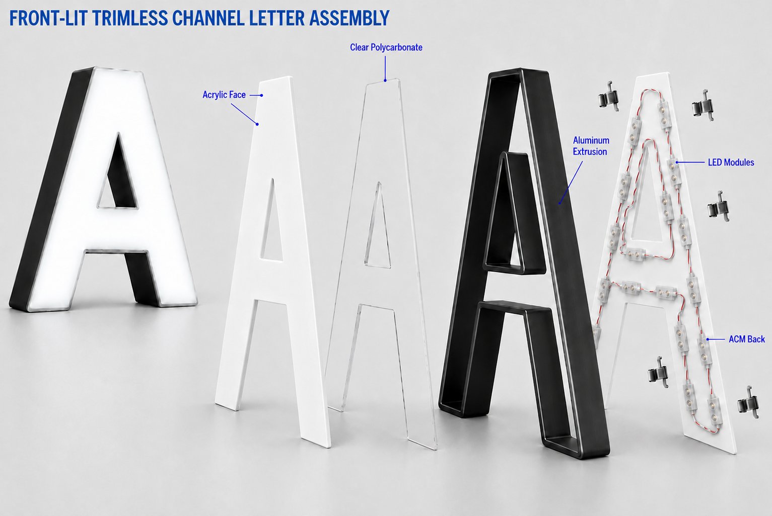
A front-lit letter lights up through its face. This version has a translucent acrylic face with an aluminum trim border, side returns formed from aluminum, and a back made of aluminum or ACM (aluminum composite material). The LEDs sit inside the letter body, behind the face.
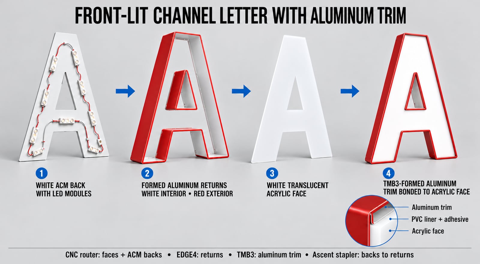
Three Ascent machines make the parts, including the aluminum trim, and the stapler joins them:
| Machine | What it does |
|---|---|
| CNC router | Cuts the acrylic faces and the aluminum or ACM backs. |
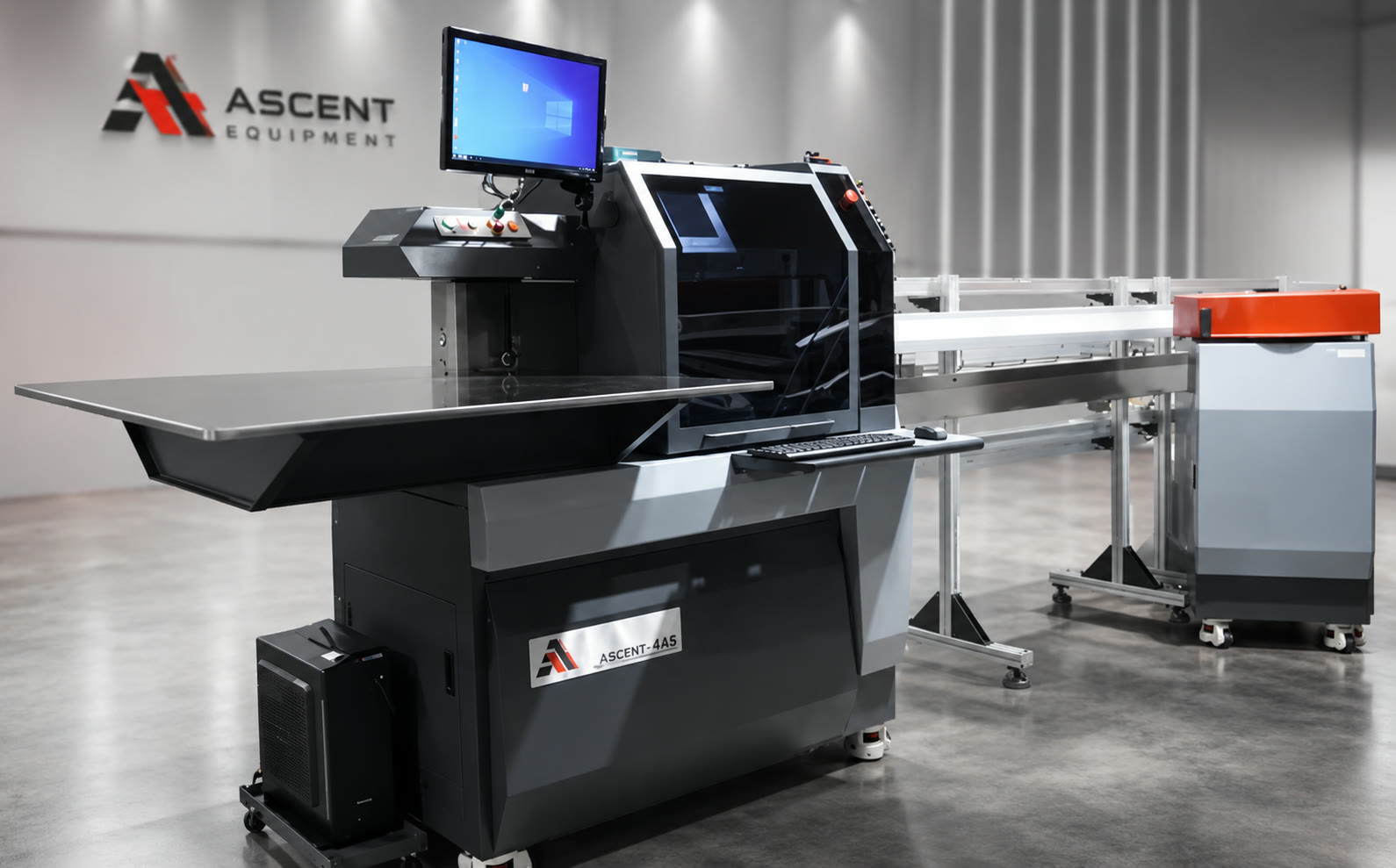
| EDGE4 | Notches, flanges, and bends the aluminum side returns, and punches drain and connection holes. |
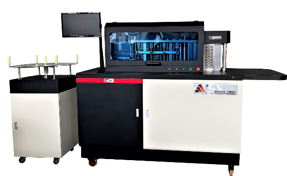
| TMB3 | Makes the aluminum trim: it turns flat aluminum coil into trim cap and forms it around the letter shape. |
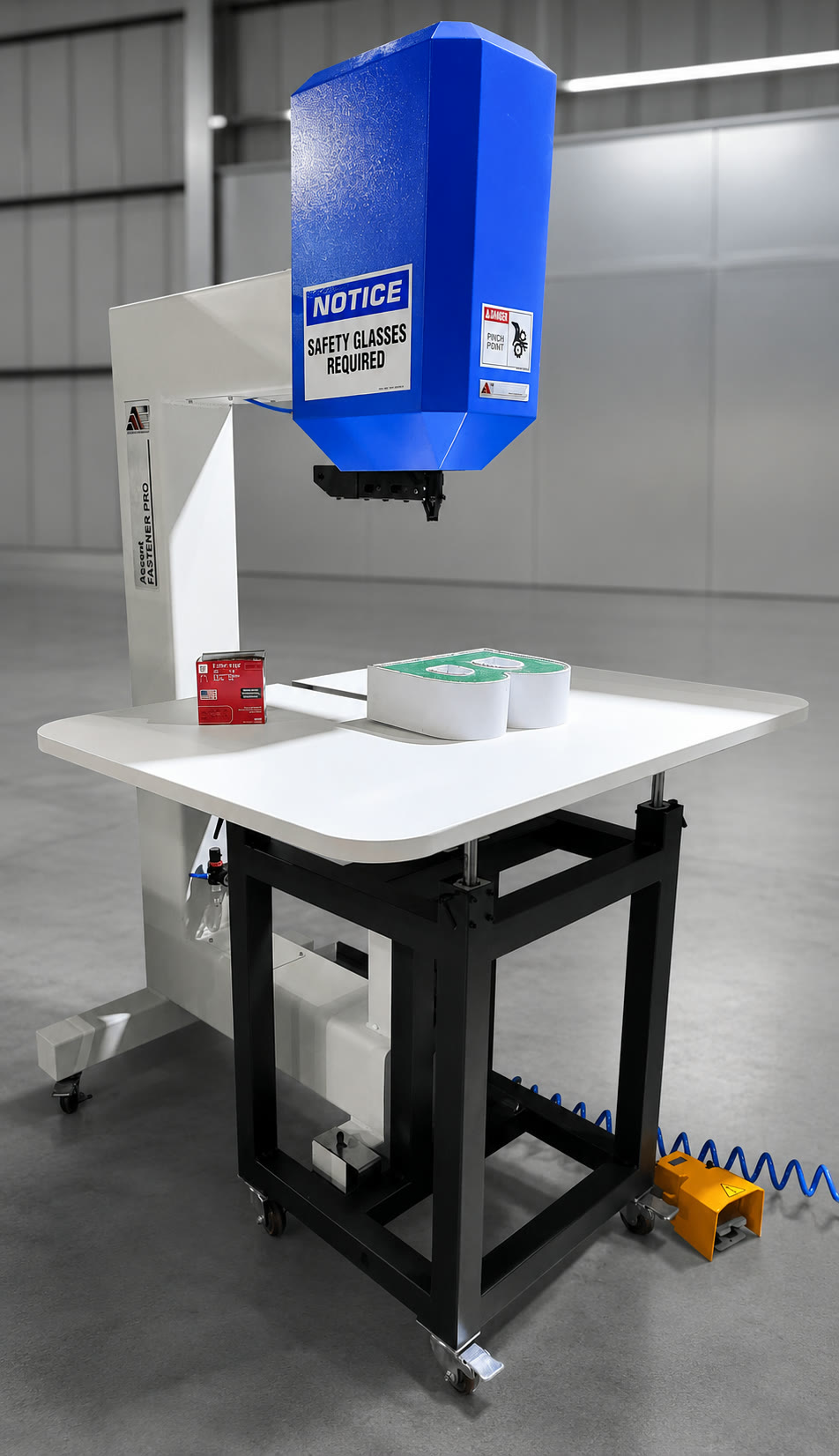
| Stapler | Fastens the back to the returns. |
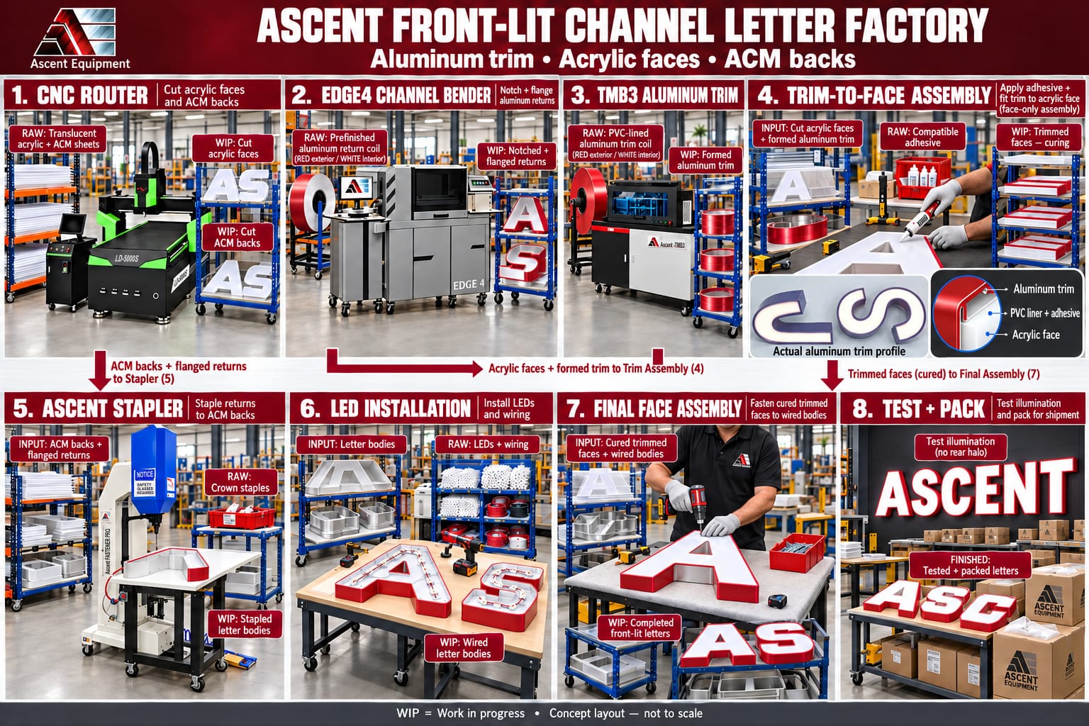
The EDGE4 makes the letter body, and the TMB3 makes the aluminum border around the acrylic face. Because the EDGE4 forms the returns, the TMB3 can stay on trim, and the two machines can run at the same time.
1. Prepare the letter files
Make clean vector outlines for each letter, including the inner openings in letters like A, B, O, and R.
Prepare matching files for the acrylic face, the back, the side returns, and the trim. These parts need different allowances for material thickness and for the trim profile, so they fit together. Confirm the allowances with a test letter before you run the job.
2. Cut the faces and backs on the CNC router
- Cut the translucent acrylic faces.
- Cut the backs from the material your sign construction calls for, such as aluminum or ACM.
- Include mounting and wiring holes where you need them.
- Remove chips and burrs, and clean the face edges before bonding.
3. Form the side returns on the EDGE4
Load aluminum coil in the color, thickness, and letter depth you need. The EDGE4 cuts the notches, forms the bottom flange, makes the bends, and adds the connection features that complete the letter perimeter. It can also punch drain holes. It processes aluminum coil up to 0.063 inch thick.
4. Make the aluminum trim on the TMB3
The TMB3 makes the aluminum trim, so you don't buy plastic trim cap or form it by hand. To make the trim:
- Load Ascent aluminum trim coil on the TMB3. The coil has a PVC lining on the inside. White, black, and red are kept in stock, and other colors can be ordered.
- Choose the trim size, 1 inch or 2 inch.
- Load the letter file. The TMB3 folds the flat coil into the trim profile and forms it to match the acrylic face, including the inner openings.
- Let the machine cut and notch the trim. Its 360-degree cutter puts the notches in the right position at the front and the back, so the corners close cleanly.
- Check each piece against the routed acrylic face before you bond it.
The PVC lining is the surface you bond to the face, so the trim attaches the way plastic trim does, with an adhesive that suits the PVC and your face material. Aluminum trim also doesn't fade or crack the way plastic trim can.
5. Bond the trim to the acrylic face
Dry-fit the formed trim around the acrylic, and check the corners, the curves, and the closing seam.
Apply an adhesive that works with the PVC lining and your face material, hold the assembly in place, and let it cure as the adhesive's instructions say. You end up with a removable acrylic face that has an aluminum trim border.
6. Join the back to the returns with the stapler
Fit the formed return around the routed back and close the return joint. Then fasten the bottom flange to the back with the Ascent stapler.
The stapler is pneumatic and runs from a foot pedal. It drives standard 16-gauge crown staples, and its adjustable table fits letters of any depth. It works with aluminum returns from 0.040 to 0.063 inch and with backs of ACM, aluminum, or polycarbonate.
7. Install the LEDs and attach the face
Install the LED modules and wiring inside the letter body, and test the lighting before you close the letter.
Fit the trimmed face over the side returns and secure it with screws through the trim skirt into the returns. Keep the drain holes clear, and make sure the face can still be removed for service.
In order: router-cut faces and backs, EDGE4 letter bodies, TMB3 aluminum trim, bonding the trim to the face, stapling the back, LEDs, and final assembly.
Reverse-halo channel letters
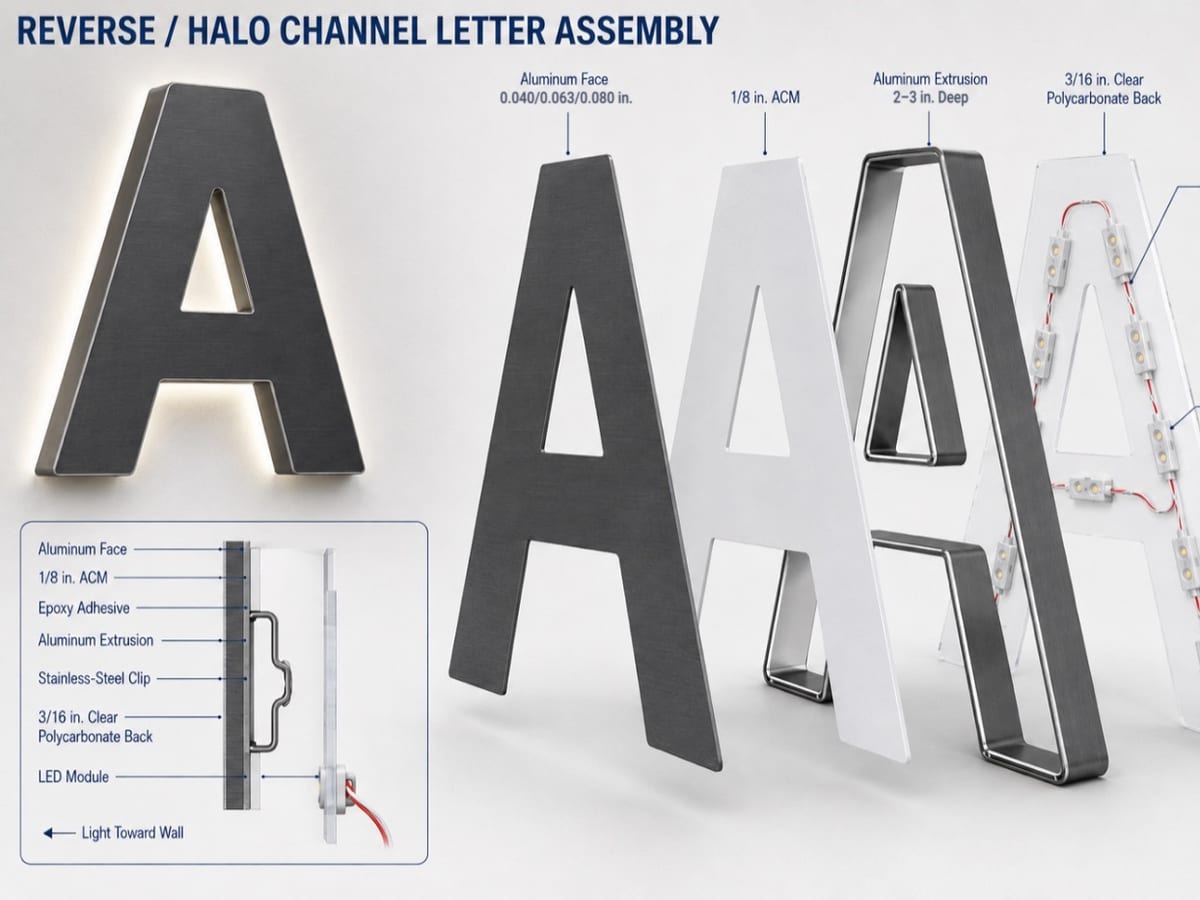
A reverse-halo letter has a solid aluminum front that blocks the light going forward. The LEDs sit inside the letter, and their light leaves through a clear rear cover and lands on the wall. The wall glows around the letter, and that glow is the halo.
This version is welded. It has mill-finish aluminum fronts and returns that are painted after welding, and a polycarbonate back. The front is welded to the return, so the back is the only way into the letter. That is why it is held on with brackets and screws and not stapled: a faulty LED module can be replaced without cutting anything.
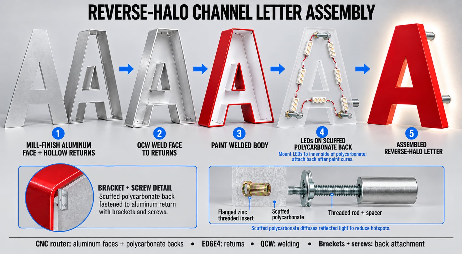
| Machine | What it does |
|---|---|
| CNC router | Cuts the aluminum fronts and the polycarbonate rear covers. |
| EDGE4 | Forms the flat mill-finish aluminum side returns, with no flange on the bottom. |
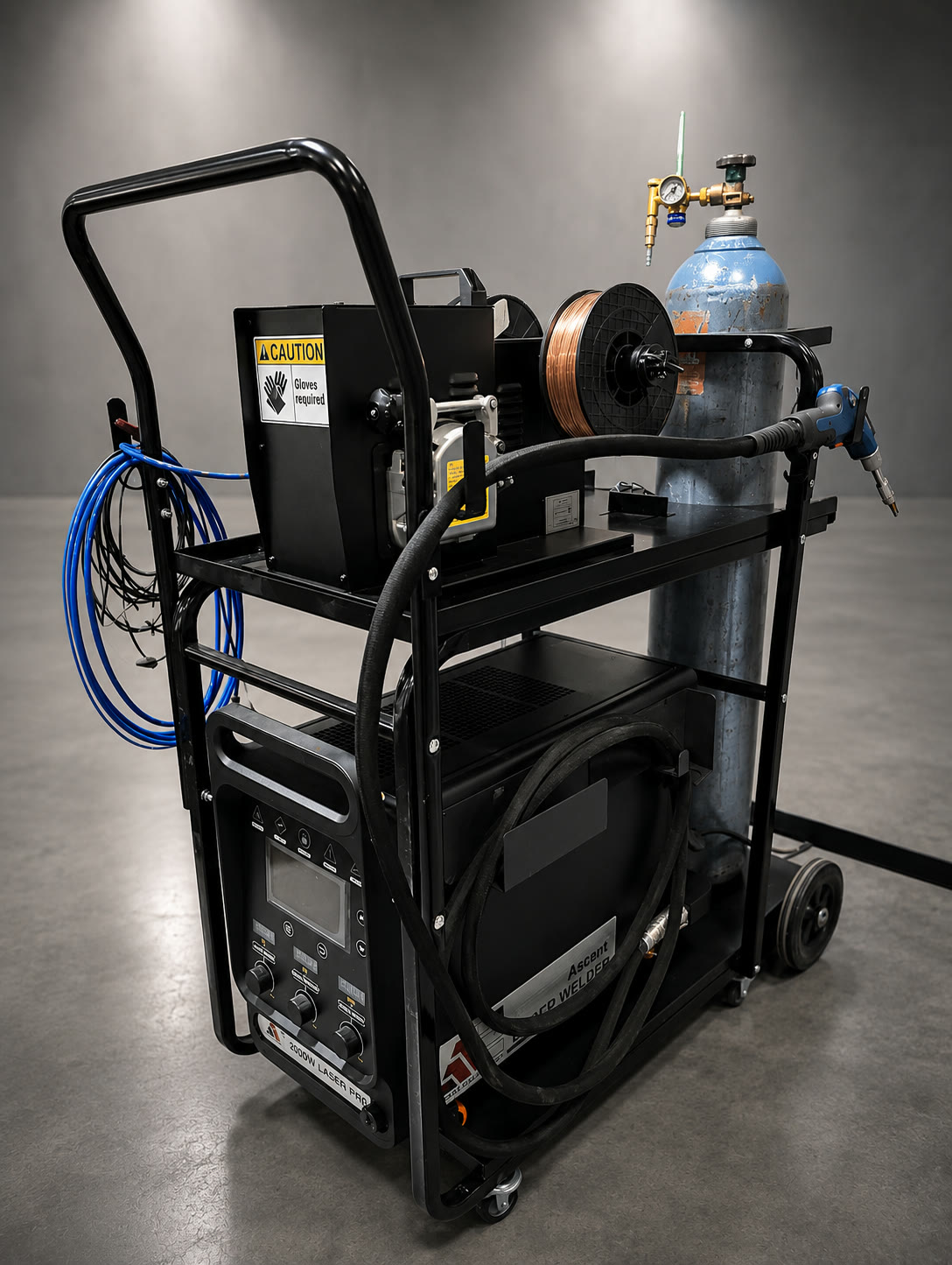
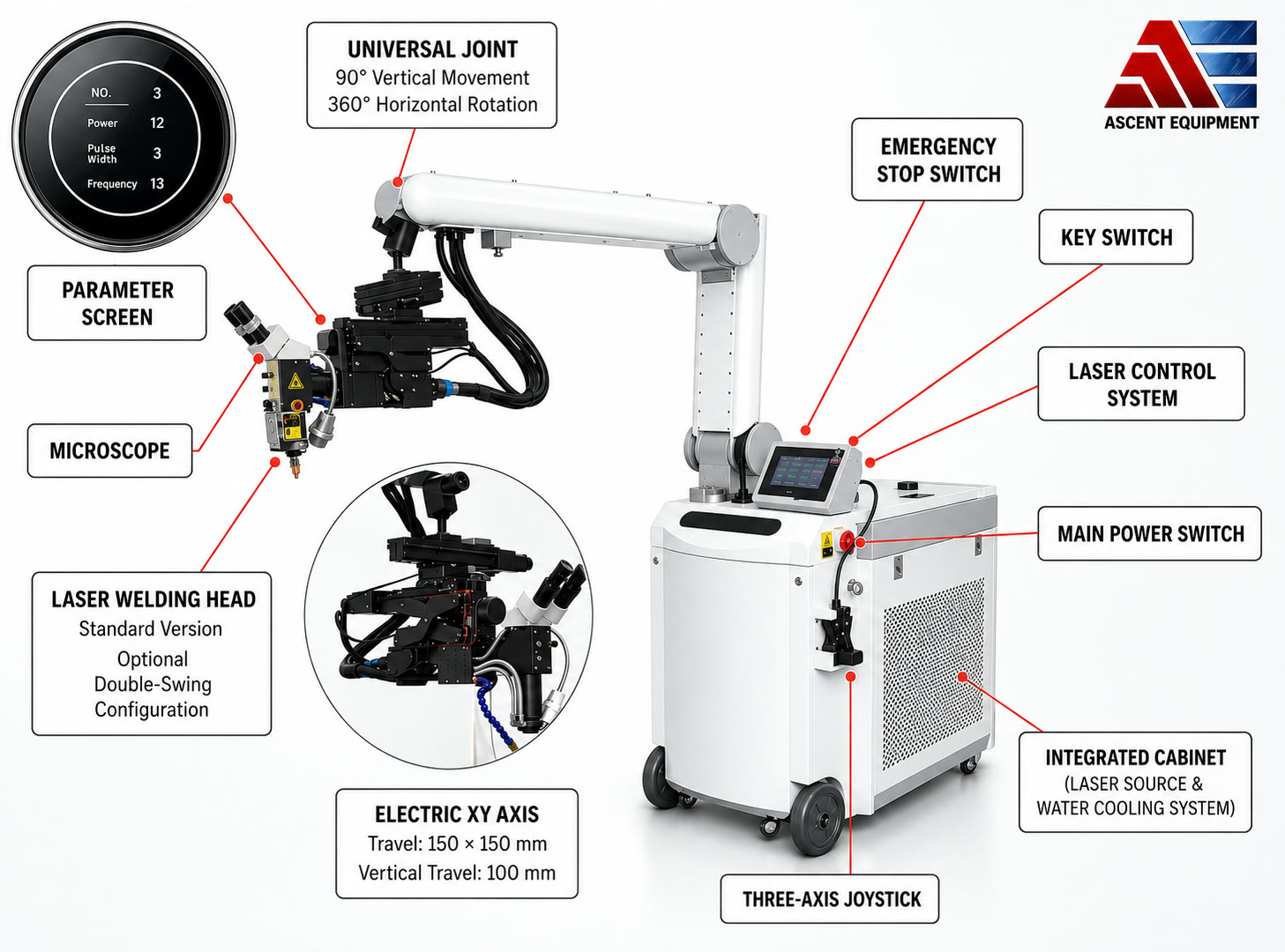
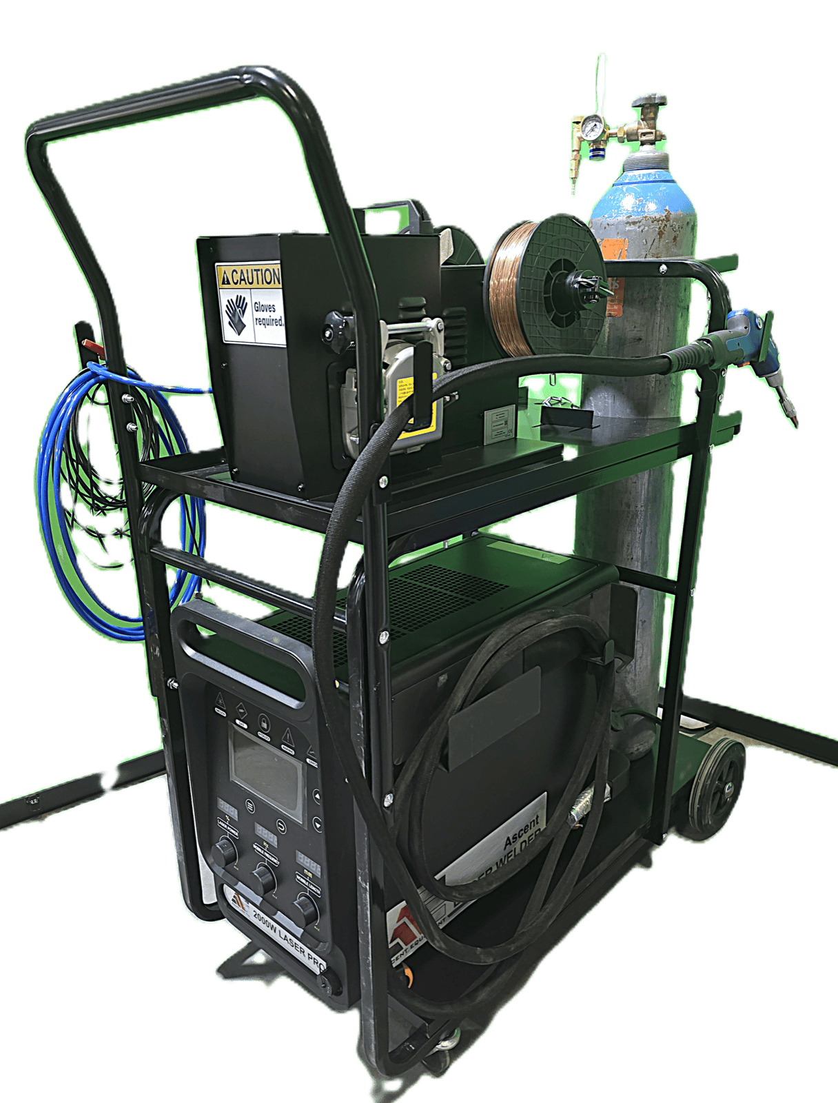
| QCW laser welder | Welds the fronts to the returns and closes the return joints. |
| Brackets and screws | Hold the polycarbonate back on the painted letter body, so the back can come off for LED service. |
1. Prepare the production files
Make matching vector outlines for the aluminum fronts, the side returns, and the polycarbonate rear covers. Include the inner openings, mounting locations, and wiring holes.
Allow for material thickness, the welded joints, and the fit of the rear cover. Confirm the fit with a test letter before you make the whole sign.
2. Cut the fronts and rear covers on the CNC router
Cut the letter fronts from mill-finish aluminum sheet on the Ascent CNC router. An Ascent laser cutter can cut them too. Cut all the inner openings, deburr the edges, and clean the areas you will weld.
Cut the rear covers from clear or frosted polycarbonate, with the mounting and wiring holes and the screw holes for the brackets. Set the covers aside until welding and painting are finished.
3. Form the returns on the EDGE4
Load mill-finish aluminum coil in the thickness and letter depth you need. Use the EDGE4's reverse-halo setup to form the outer perimeter and the inner returns. The returns are flat, with no flange on the bottom, because the front is welded to the return and the back is held on separately. Set up the connection features from your assembly drawing, and put drain holes at the lowest points of the installed letters.
Check the formed returns against the routed aluminum fronts.
4. Fit and weld on the QCW laser welder
Place the aluminum front face down. Position and clamp the returns around the perimeter and the inner openings. Keep the joints tight and the sides square. Prepare the weld areas, and set your parameters on scrap of the same alloy, thickness, and joint shape.
With the QCW laser welder:
- Tack the returns in position.
- Weld the front to the returns, from the inside where you can reach.
- Close the return joints.
- Join the inner returns to the front.
Use a balanced welding sequence to limit distortion. Inspect the welds, and dress visible joints where needed without weakening them.
The QCW is a pulsed laser, which keeps the heat-affected zone small and helps on thin aluminum. It welds aluminum from 0.020 to 0.063 inch, with fronts up to 0.080 inch, so check your front and return thickness against that range.
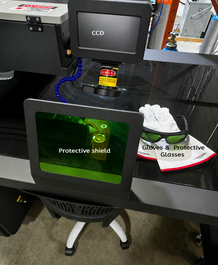
Do the welding in a laser-controlled area with proper beam containment, fume extraction, shielding gas, and laser-rated eye protection. Our laser safety guide covers what the setup needs.
5. Prepare and paint the aluminum body
Finish all welding before you paint, and let the paint cure before you install the LEDs.
Clean and degrease the assembled letter. Prepare the mill-finish aluminum with the abrasion or pretreatment your coating manufacturer specifies. Apply an aluminum-compatible primer if the coating needs one, then paint the front and the outside of the returns in the sign color. Paint the inside with a compatible reflective white, which helps spread the light.
Keep the drain holes clear, and protect threaded mounting points from paint buildup.
6. Scuff the polycarbonate back and mount the LEDs
Scuff the polycarbonate backs. The light reflects off the white interior of the letter, and the scuffed polycarbonate diffuses it, which cuts down hotspots.
Mount the LED modules on the inner side of each back, and install the hardware for the standoffs, such as threaded inserts, threaded rod, and spacers. Choose the module spacing to suit the letter size and depth, and secure the wiring. Test the lighting before the back goes on.
7. Fasten the back with brackets and screws
Once the paint has cured, attach brackets to the inside wall of the painted return, then screw each LED-equipped back to the brackets. Use stainless brackets and screws, and keep the drain paths open.
Don't staple or glue the back on. The front is welded to the return, so the back is the only way to reach the LEDs later. Screws let you take the back off, replace a faulty LED module, and put the back on again, without cutting or unwelding anything.
Drill the screw holes in the polycarbonate slightly oversize so it can expand and contract, and leave enough wiring slack to lift the back clear of the letter.
8. Test the halo and mount the letters
Test the illumination and the connections before the letters ship. At the wall, install the letters on standoffs at the distance your design specifies. Check for an even halo and for visible LED hotspots. Wall color, texture, LED placement, and mounting distance all affect the result.
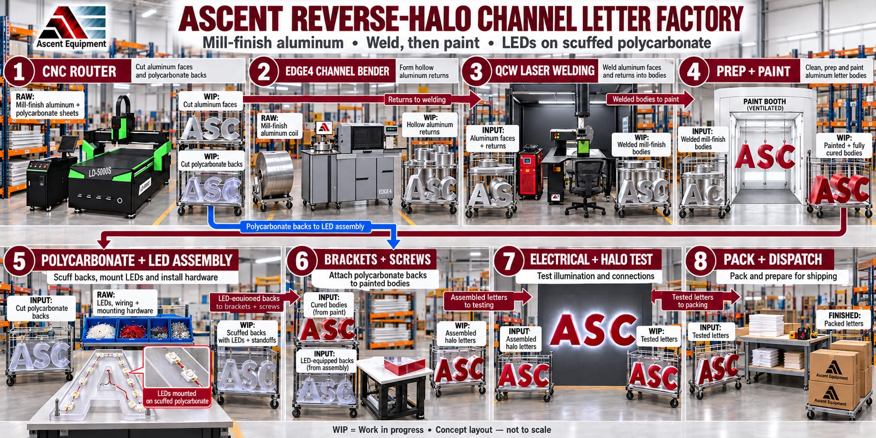
In order: router-cut aluminum fronts and polycarbonate backs, EDGE4 returns, QCW welding, surface preparation and painting, LEDs on the polycarbonate backs, brackets and screws, testing, and standoff mounting.
Putting the two styles side by side
Both styles start the same way. The router cuts the flat parts, and the EDGE4 forms the returns. The difference is in how the parts come together. Front-lit letters use the TMB3 to make the aluminum trim and the stapler to join the back to the flanged returns. Reverse-halo letters have flat returns with no flange. The QCW welds the front to the returns, and brackets and screws hold the back on so it can come off for service.
If you would rather not weld reverse-halo letters at all, our post on making reverse-halo letters without welding covers that method.
Want to talk through which machines fit your shop? Contact us. Installation and operator training are included with every Ascent machine.
Learn more
- Ascent EDGE-4 CNC bending machine
- Ascent TMB-3 bending and trim machine
- Ascent pneumatic channel letter stapler
- Ascent CNC routers
- Ascent QCW laser welder
- How to make a channel letter the Ascent way with the TMB-3
- Making aluminum trim with the TMB-3
- Ascent laser safety guide
Product details were checked against the Ascent Equipment site on October 11, 2026. Specifications and configurations can change, so confirm them with us before you order.