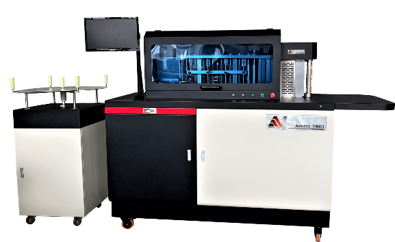

Trimless and reverse-halo letters look nothing alike, but a shop can make both with the same short list of equipment: an Ascent CNC router, an Ascent 5AS bender, Ascent aluminum extrusions, and stainless-steel clips. The trimless letters have no trim cap, and the reverse-halo letters have nothing welded.
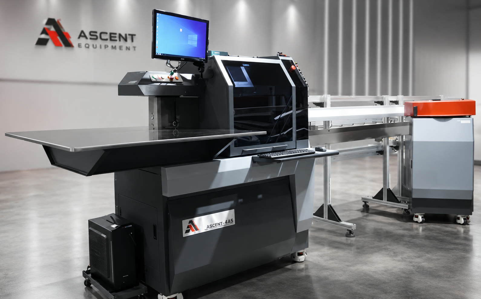
This guide follows both builds the way they run on a shop floor. The router cuts the flat parts while the 5AS bends the returns, and the two meet at the assembly bench. The 4AS does the same bending work on these two styles, so everything here applies to it as well. The 5AS adds F-trim.
The pictures show how each letter goes together. They don't replace a fabrication drawing, so use the profile, panel thicknesses, fasteners, and electrical design approved for each job.
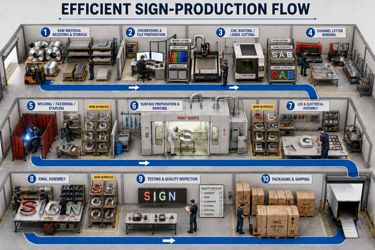
The shop floor at a glance
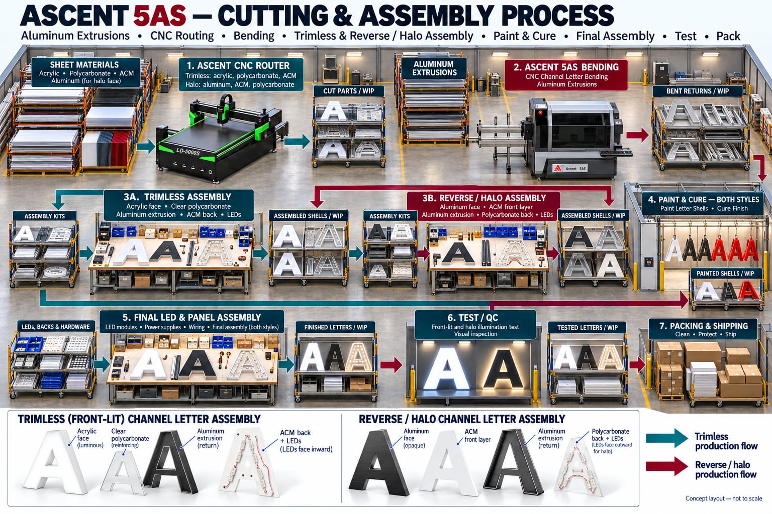
Stage incoming sheet and extrusions in front of each workstation, and put checked work in progress (WIP) on a labeled cart after it. Keep jobs separate, protect finished surfaces, and release parts to the next station only after they pass their checks.
Cutting and bending run side by side. Their checked outputs meet at the assembly bench as one complete letter kit. They aren't two operations done one after the other on the same part.
What the system uses
| Part | What to know |
|---|---|
| Aluminum extrusion | The hollow return. It comes primed white with epoxy, so you can leave it white or paint over it, and other colors are available. It comes in four sizes, 1.37, 2, 3, and 4 inches, and it is a UL/RU Recognized Component for indoor and outdoor letters up to 66 inches. |
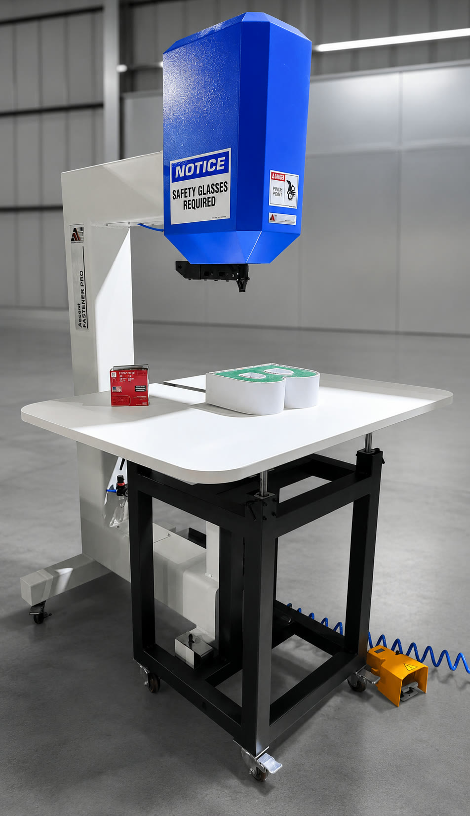
| Stainless-steel pins, 6 mm | Tiny pins driven by the pneumatic gun that comes with the bender. They close the return joints and pin the clear polycarbonate layer to the extrusion on a trimless letter, so there is no clamp and no magnet table. |
| Stainless-steel clips | They hold the back panel on without welding or glue. The 8 mm clip is for front-lit letters and the 5 mm clip is for reverse-halo letters. There are also 3 mm and 10 mm clips for the 1.37-inch and 4-inch extrusions. |
| Sheet material | Acrylic, clear polycarbonate, ACM (aluminum composite material), and aluminum, all cut on the CNC router. |
Already own a 4AS or 5AS? You can order extrusions, clips, pins, and the pneumatic gun on our materials ordering page.
Trimless (front-lit) channel letters
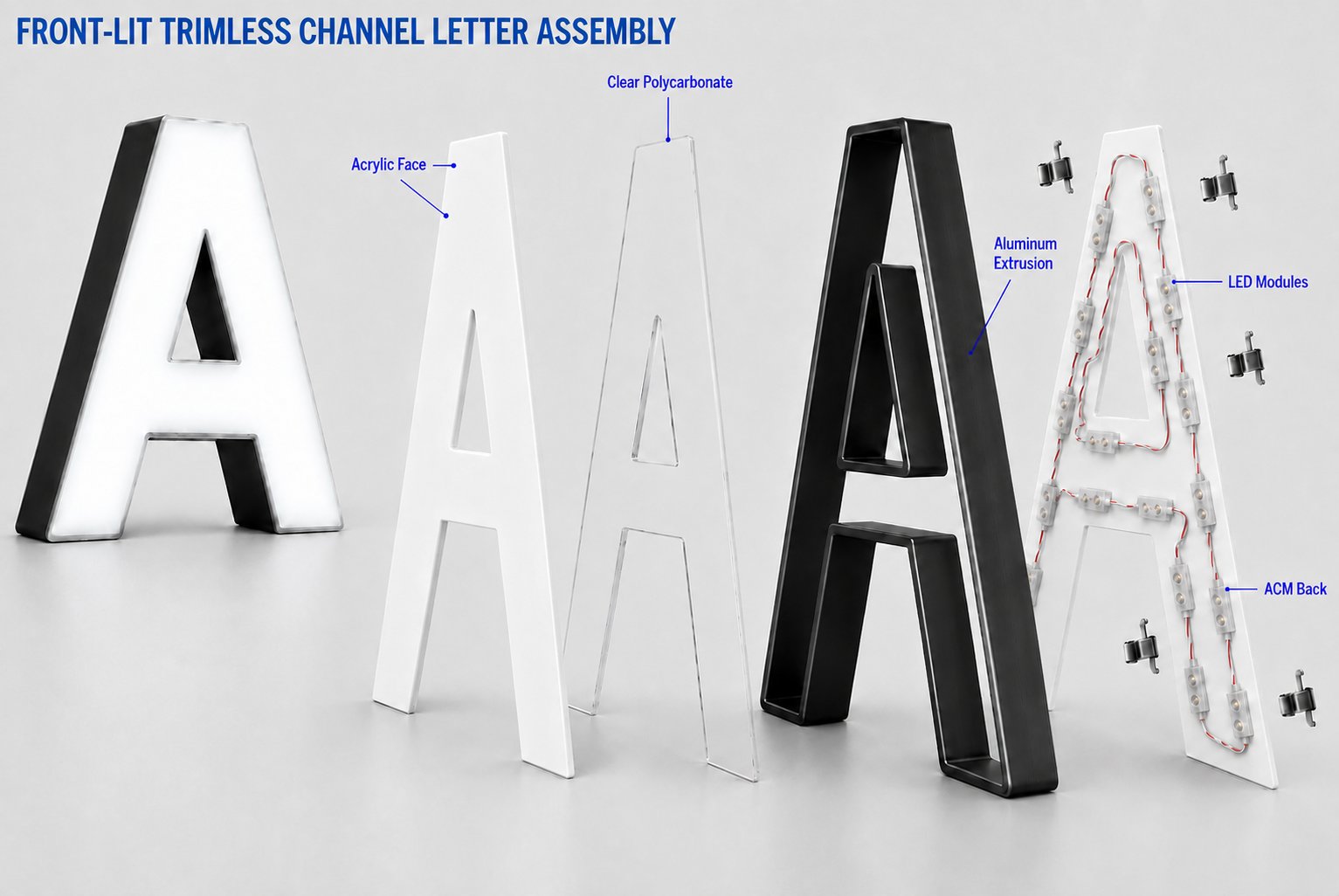
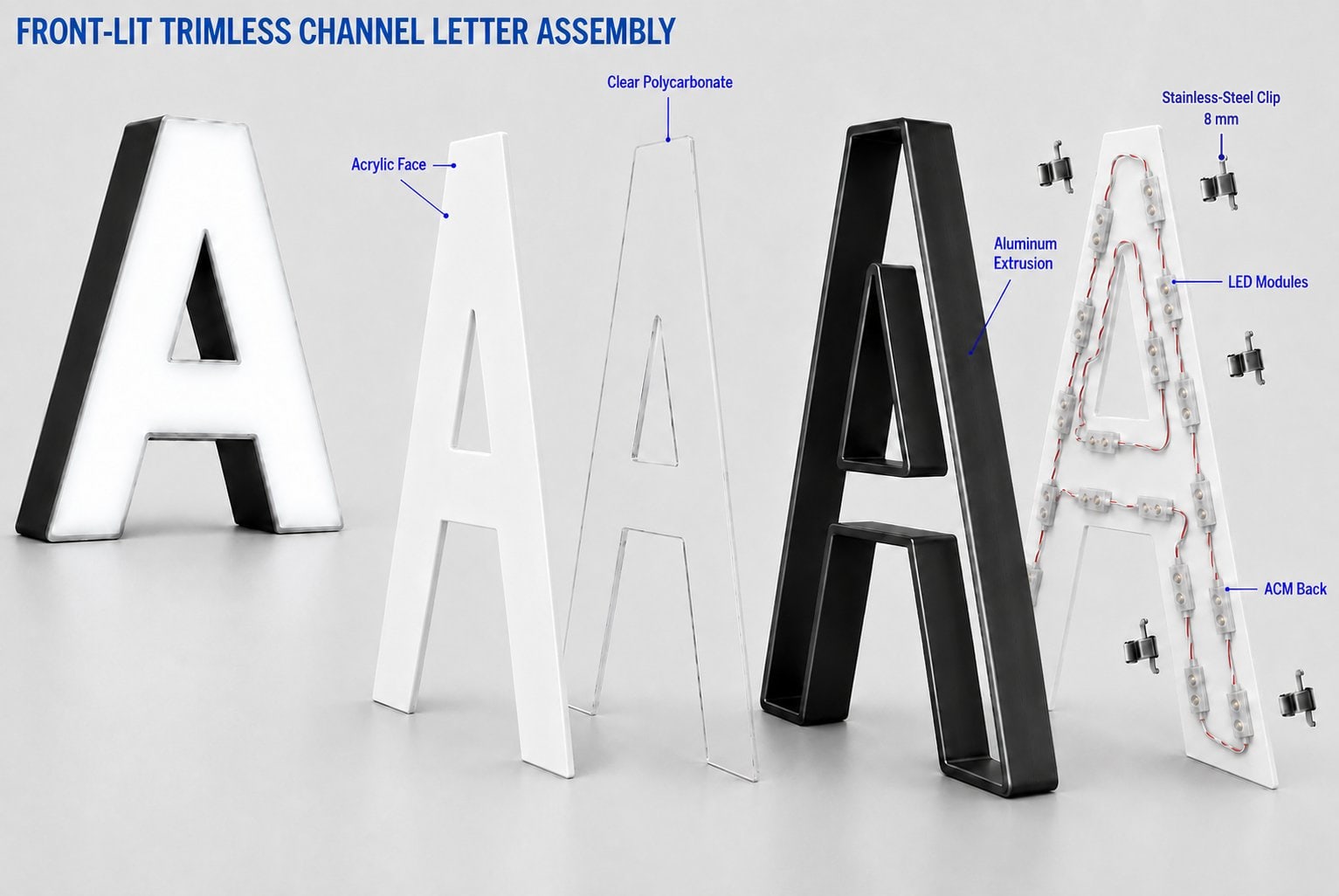
A trimless letter lights up through its acrylic face, and there is no plastic or aluminum trim cap around the edge. The extrusion is the return. A clear polycarbonate layer is pinned to it with tiny 6 mm pins, the acrylic face is glued on with optically clear glue, and the LED modules sit on an ACM back.
| Material | What it does |
|---|---|
| Acrylic | The light-transmitting front face. |
| Clear polycarbonate | A reinforcing layer behind the acrylic face, pinned to the extrusion. |
| Aluminum extrusion | The bent, hollow return. |
| ACM | The back panel that carries the LED modules. |
| Stainless-steel clips, 8 mm | Hold the ACM back on the return. |
| LEDs and electrical parts | Modules, wiring, connectors, and a suitable power supply. |
| Stainless-steel pins, 6 mm | Pin the polycarbonate layer to the extrusion. The pneumatic gun comes with the bender. |
| Optically clear glue | Glues the acrylic face on. |
| Sealant and paint | As the approved job detail specifies. |
1. Prepare the job and stage the materials
Confirm the artwork, letter depth, face color, finish, mounting details, and electrical layout. Prepare the router file and the bending file from the same approved geometry, so the parts fit.
Stage the acrylic, clear polycarbonate, and ACM sheets at the router, and the straight extrusions at the 5AS. Identify every part by job and letter.
2. Cut the face layers and ACM backs on the router
Cut the acrylic faces, the clear polycarbonate reinforcing layers, and the ACM backs on the Ascent CNC router. Choose tooling, feeds, workholding, and dust extraction to suit each material. Deburr the parts, protect the visible surfaces, and check a sample fit before you cut the whole job.
Put the checked parts on the cut-parts cart.
3. Bend the extrusion returns on the 5AS
Load the extrusion and the matching letter file into the 5AS. Use the approved profile settings to process and bend the outer outline and any inner openings, such as the counter of an A. Check the shape and the depth against the cut parts, then move the bent returns to their cart.
4. Close the returns and fit the shell
Bring one complete kit of cut parts and bent returns to the assembly bench. Close the return joints with the pneumatic gun and the stainless-steel pins, following the approved assembly detail.
Dry fit the acrylic, the polycarbonate layer, and the ACM back. Then take off anything that must stay out of the paint area, and stage the checked shells on the assembled-shells cart.
5. Paint and cure
Move the shells to the paint area. Prepare and paint the aluminum return surfaces that need the chosen finish. A white return can stay in its epoxy primer, and other colors paint over it.
Keep the acrylic, the polycarbonate, the LED modules, and the electrical parts out of the paint operation. Let the finish cure as the coating instructions say, protect it, and move the shells to the painted-shells cart.
6. Install the LEDs and finish the panels
Mount the LED modules on the inward-facing side of the ACM back, so they light the acrylic face through the clear polycarbonate layer. Route and secure the wiring without pinching it at the panel edges.
Pin the clear polycarbonate layer to the extrusion with the 6 mm pins and the pneumatic gun, then glue the acrylic face on with optically clear glue. Let the glue cure as its instructions say. Then fit the ACM back with its 8 mm clips and the approved sealing details.
Because clips hold the back and nothing is welded, the back can come off again for wiring or service without cutting the letter apart. Move the finished letters to their cart.
7. Test and inspect
Check the electrical operation and the front illumination. Look for even light, dark areas, and hot spots. Inspect the paint, the face edges, the joints, the panel fit, the fasteners, and the wiring.
Check the mounting arrangement and any drainage or ventilation details against the approved drawing, and fix any defects before the letter moves on to the tested-letters cart.
8. Pack and release
Protect the acrylic faces and the painted surfaces with nonabrasive packaging. Keep the letter from moving in transit, and protect the cables and mounting hardware. Include the mounting pattern or drawings, the identified hardware, and the electrical instructions the job needs. Label the package, and release only checked letters.
Release checklist for trimless letters
- The acrylic and the clear reinforcing layer match the approved face shape, the polycarbonate is pinned, and the acrylic is glued on.
- The return is hollow, and the front has no plastic trim cap.
- The LED modules are secured to the ACM back and face inward.
- The finish has cured before final assembly and packing.
- Front illumination, electrical connections, and mounting details pass inspection.
Reverse-halo channel letters
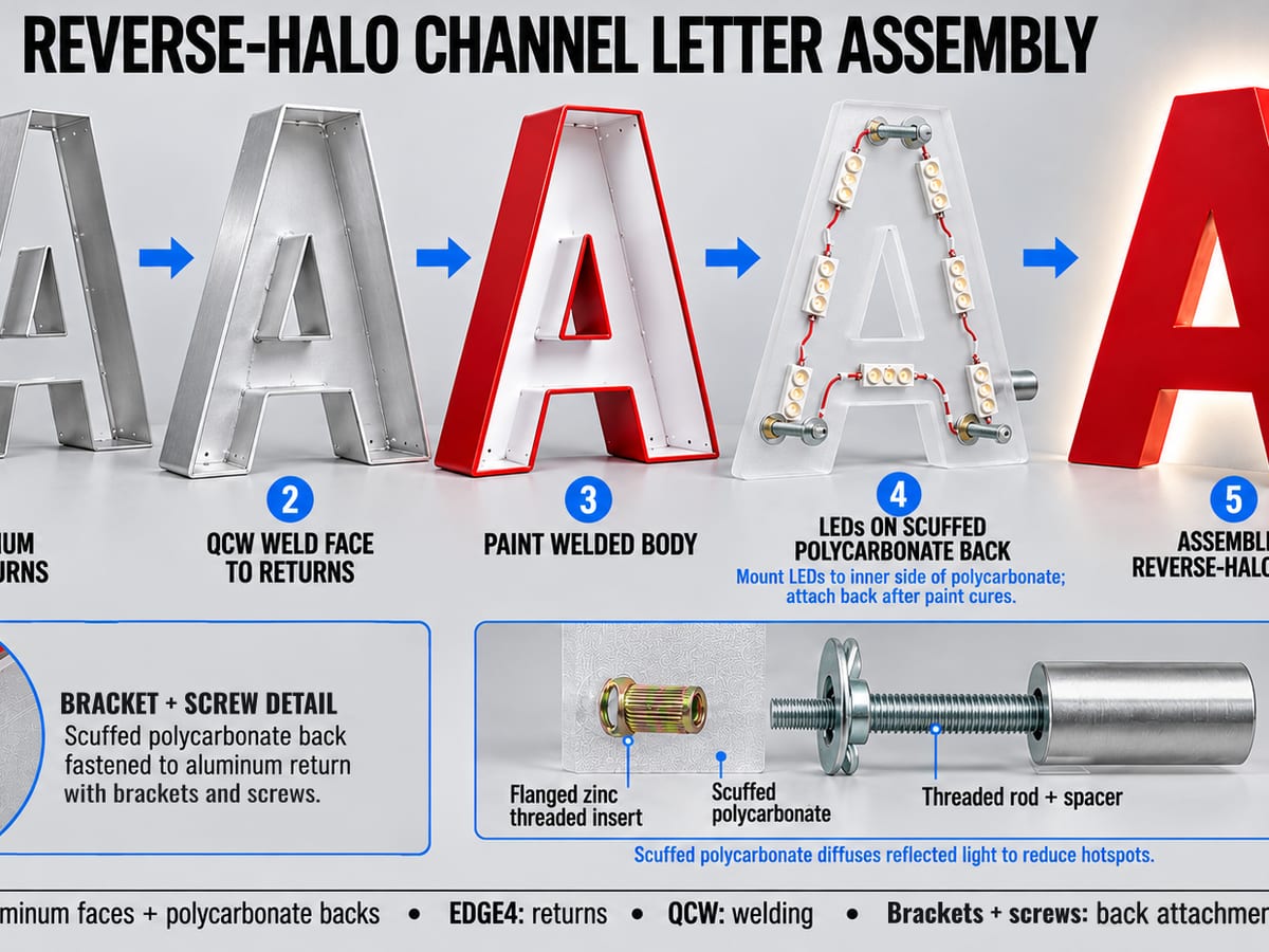
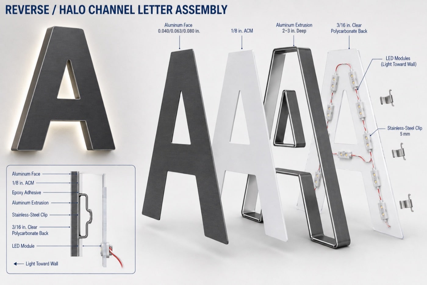
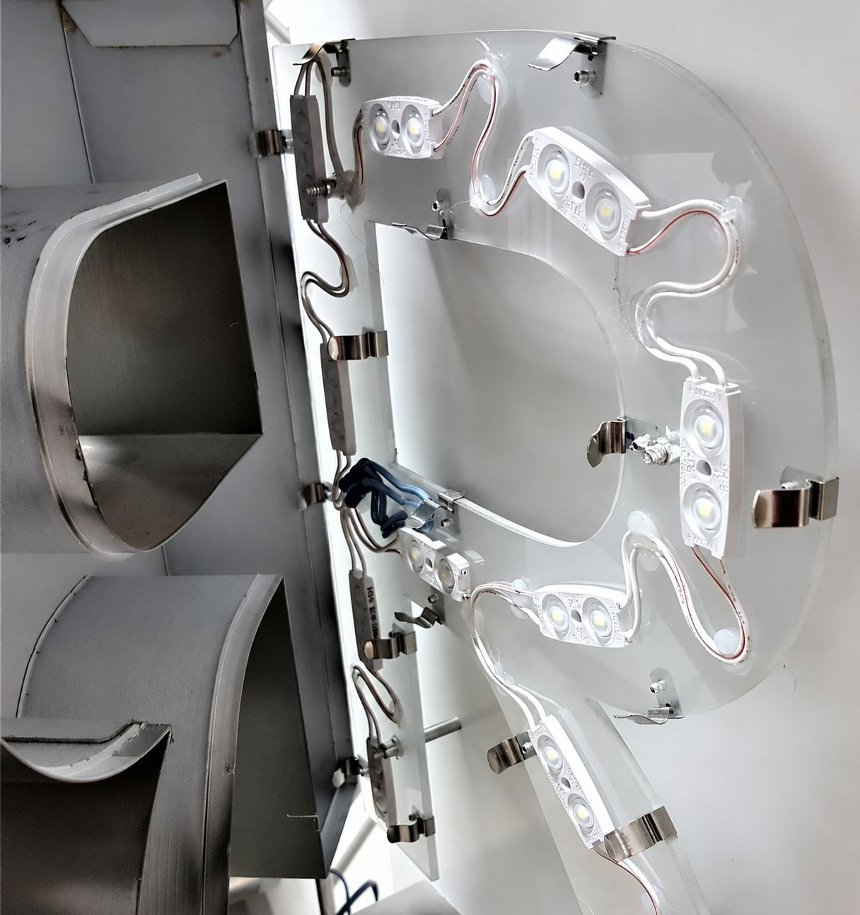
A reverse-halo letter has an opaque aluminum front that blocks the light going forward. The LEDs face the other way, through a clear polycarbonate back, and throw their light onto the wall behind the letter. That glow around the edge is the halo.
The front layers and the extrusion are joined mechanically and with the bonding details in the job spec, so there is no welding station. The aluminum and the ACM belong at the front. The polycarbonate is the back.
| Material | What it does |
|---|---|
| Aluminum sheet, 0.040 to 0.080 inch | The opaque, visible front face. |
| ACM, 1/8 inch | A front layer behind the aluminum face. |
| Aluminum extrusion, 2 to 3 inches deep | The bent, hollow return. |
| Clear polycarbonate, 3/16 inch | The rear, light-transmitting panel that carries the LEDs. |
| Stainless-steel clips, 5 mm | Hold the polycarbonate back on the return. |
| Epoxy adhesive | Bonds the face and ACM layer to the return, as the approved detail specifies. |
| LEDs, mounting spacers, and paint | Modules and wiring, the standoffs, and the finish. |
1. Prepare the job and stage the materials
Confirm the artwork, letter depth, face finish, wall surface, mounting standoff, and the halo you want. Prepare the router file and the bending file from the same approved geometry.
Stage the aluminum, ACM, and clear polycarbonate sheets at the router, and the straight extrusions at the 5AS. Identify every part by job and letter.
2. Cut the aluminum and ACM fronts and the polycarbonate backs
Cut the aluminum faces, the matching ACM layers, and the clear polycarbonate backs on the Ascent CNC router. Pick tooling, workholding, feeds, and chip extraction for each material, aluminum included. Deburr the parts without marking the visible faces.
Put the checked parts on the cut-parts cart.
3. Bend the extrusion returns on the 5AS
Load the extrusion and the matching file into the 5AS. Bend the outer outline and any inner openings with the approved profile settings. Check the hollow return against the aluminum and ACM fronts and the polycarbonate back, and move the checked returns to their cart.
4. Assemble the opaque front and the return
Stage a complete kit at the bench. Form and close the return with the approved mechanical joining method, which is the pneumatic gun and the stainless-steel pins.
Fit the ACM layer and the aluminum face in the order your assembly drawing shows, using the specified fasteners and epoxy where the detail calls for them. Keep the inside hollow.
Dry fit the polycarbonate back and its clips, then take them off before painting. Move the shells to the assembled-shells cart.
5. Paint and cure the face and returns
Prepare and paint the aluminum face and the return surfaces that need the chosen finish. Keep the polycarbonate back, the LEDs, and the wiring out of the paint operation.
Check that the paint is compatible with the front layers and the epoxy, then let it cure fully. Protect the shells and move them to the painted-shells cart.
6. Prepare the LED back and finish the assembly
Fit the LED modules and wiring to the clear polycarbonate back, using the approved layout and attachment method. Point the modules toward the wall, so their light goes out through the back.
Check that the polycarbonate still transmits light and that the face stays opaque. Secure the back with the 5 mm clips, protect the wiring at the edges, and fit the mounting spacers. Move the complete letters to their cart.
The clips are the reason a bad LED module is a short job. Lift the back off, replace the module, and clip the back on again. Nothing was welded, so nothing has to be cut.
7. Test the halo and inspect
Mount a sample letter or a finished letter on a test surface at the standoff you plan to use. Switch on the LEDs and look at the halo. It should be even, with no dark patches and no light leaking around the front. The aluminum face must stay opaque.
Inspect the finish, the bond or fasteners behind the face, the clips, the panel fit, the wiring, and the mounting arrangement. Fix any defects, then stage the approved letters on the tested-letters cart.
The standoff and the wall change what the halo looks like. Our post on making reverse-halo letters has a rule of thumb for the distance, and it explains why a smooth, light wall gives the cleanest glow.
8. Pack and release
Protect the painted faces and returns and the polycarbonate backs. Keep any pressure off the LEDs, the clips, and the mounting spacers. Pack the identified spacers, hardware, mounting patterns, and electrical instructions with the job. Label every letter and carton, and release only inspected assemblies.
Release checklist for reverse-halo letters
- The aluminum face and the ACM layer are at the front.
- The return is hollow, and the rear panel is clear polycarbonate.
- The LED modules are on the rear panel and aimed at the wall.
- The face and returns are painted and cured before the electronics go in.
- The front stays opaque, and the halo passes testing at the planned standoff.
Trimless and reverse-halo side by side
| Trimless (front-lit) | Reverse-halo | |
|---|---|---|
| Light goes | Out through the front | Out the back, onto the wall |
| Front | Acrylic face with a clear polycarbonate layer | Opaque aluminum face with an ACM layer |
| Back | ACM back with the LEDs | Clear polycarbonate back with the LEDs |
| Clip size | 8 mm | 5 mm |
| Trim cap | None | None |
| Welding | None | None |
Quick answers
Do I need a welder for reverse-halo letters?
No. The returns are bent from extrusion and closed with pins, the front layers are bonded or fastened as the job spec says, and the back is clipped on.
Does the 4AS make these letters too?
Yes. The 4AS and 5AS process the same materials, and the 5AS adds F-trim.
How big can the letters be?
Letters can be as small as 3 inches tall. The extrusion system is a UL/RU Recognized Component for indoor and outdoor letters up to 66 inches.
What comes with the machine?
The pneumatic gun comes with the bender. Installation and operator training are included, and training typically takes three days.
Want to talk through which machines fit your shop? Contact us. Installation and operator training are included with every Ascent bending machine.
Learn more
- Ascent 5AS channel letter bending machine
- Ascent 4AS channel letter bending machine
- Ascent CNC routers
- Order extrusions, clips, pins, and the pneumatic gun
- How to make trimless channel letters
- How to make reverse-halo channel letters
- The benefits of the Ascent profiles system
Product details were checked against the Ascent Equipment site on October 11, 2026. Specifications and configurations can change, so confirm them with us before you order.